
RFLink: Wiring Details and Hardware Requirements
3-1-2022
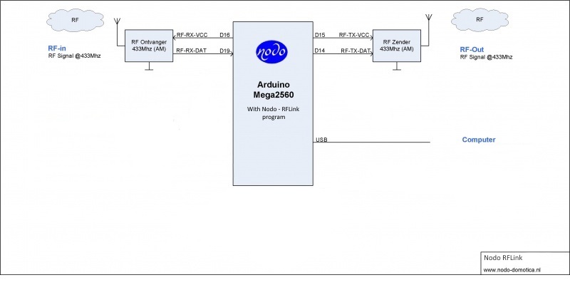
This page holds wiring details for various RF transmitter, receiver and transceiver modules for 433 mhz, 868mhz and 2.4 Ghz.
If you have wiring diagrams for other modules that you used with RFLink send a mail with details and we will add it to the page.
Hardware Requirements:
You will need the following parts:- RFLink firmware
- Arduino Mega 2560
- RF Receiver (or RF Transceiver)
- RF Transmitter (optional)
You can use one RF module for 433mhz or 868mhz or 315mhz or 915mhz. If you want to cover two frequencies you will need two arduino mega's
You can also use a 2.4Ghz module with or without one of the previously mentioned modules.
Using a separate RF receiver and RF transmitter:
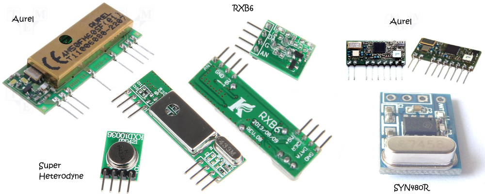
Preferred are Aurel RF receivers. Alternatively a "super heterodyne" or a R6B receiver can be used.
For transmitting a low cost 433 RF transmitter can be used.
However, the receiver that is often sold in a bundle with the cheap
Chinese RF transmitter is not performing very well. It has a lot of noise that leads to bad reception.
(see the note below!)
If building this yourself is too complicated or you dont have the time, then you can also buy
a ready made RFLink Gateway board at the Nodo webshop
Receivers and Transmitters:
Various receivers/transmitters/transceivers have been tested.
For best results use one of the following receivers:
Like "Aurel", "Super Heterodyne", "RXB6" and "SYN480R"
Note: you can use a 433Mhz, 315Mhz, 915Mhz or 868Mhz module to adjust the frequency to your needs.
Make sure you use a frequency that is legal in your country/region.
Aurel RTX MID 5v:
If you would like to use the Aurel RTX MID 5v Transceiver the pinout is:
Pin 1 = Antenna
Pin 2 = Ground
Pin 3 = Not Connected
Pin 4 = MEGA tx3/Pin 14 (TX Data)
Pin 5 = MEGA rx3/Pin 15 (-RX/TX- toggle signal!)
Pin 6 = MEGA Pin 22 (TX Enable)
Pin 7 = Ground
Pin 8 = optional: 20k resistor to ground
Pin 9 = MEGA rx1/Pin 19 (RX Data)
Pin 10= MEGA VCC (Also connect here a 100nf to ground)
RXB6:
If you would like to use the RXB6 receiver the pinout is:
Pin 1 = Antenna
Pin 2 = Not Connected / Ground
Pin 3 = Not Connected / Ground
Pin 4 = Not Connected
Pin 5 = MEGA tx2/Pin 16 (RX VCC)
Pin 6 = Not Connected
Pin 7 = MEGA rx1/Pin 19 (RX Data)
Pin 8 = Ground
In combination with the cheap Chinese transmitter (XD-FST FS1000A):
XD-FST FS1000A:
Pin 1 = Ground
Pin 2 = MEGA rx3/Pin 15 (TX VCC) (~3 - 12 volts)
Pin 3 = MEGA tx3/Pin 14 (TX Data)
Pin 4 = Antenna (when a pin is connected, otherwise use the antenna solder contact
FS1000A Output power improves with higher voltages. An increase from 5 to 12 volts raises power with 10db.
The increase in VCC will also result in a slightly lower frequency making it easier to control RTS devices.
RXB6 optimization (not required!) to improve reception:
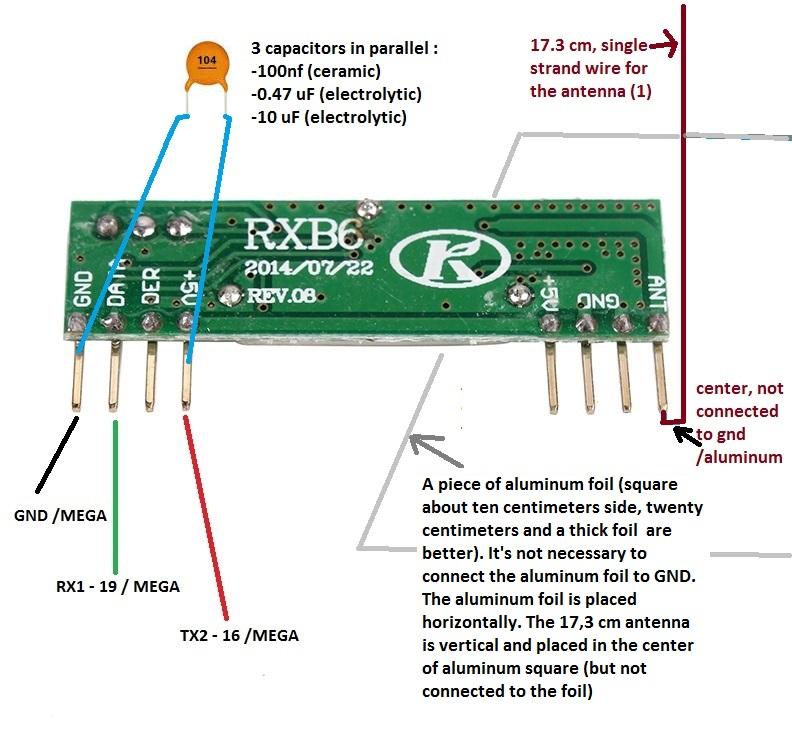
The above diagram also has some interesting improvements when using the RXB6 module courtesy of Snips.
Note that these improvements are optional for the RXB6. They can be added to other receiver modules as well and might improve performance with these modules too.
They are not at all needed when you use an Aurel receiver/transceiver.
SYN480R:
If you would like to use the SYN480R receiver the pinout is:
Pin 1 = VCC
Pin 2 = MEGA rx1/Pin 19 (RX Data)
Pin 3 = Ground
Pin 4 = Antenna
In combination with the cheap Chinese transmitter (XD-FST FS1000A):
XD-FST FS1000A:
Pin 1 = Ground
Pin 2 = MEGA rx3/Pin 15 (TX VCC) (~3 - 12 volts)
Pin 3 = MEGA tx3/Pin 14 (TX Data)
Pin 4 = Antenna (when a pin is connected, otherwise use the antenna solder contact
FS1000A Output power improves with higher voltages. An increase from 5 to 12 volts raises power with 10db.
The increase in VCC will also result in a slightly lower frequency making it easier to control RTS devices.
Qiachip WL101 + WL102:
If you would like to use the Qiachip WL101 superheterodyne receiver and WL102 transmitter set, the pinout is:
WL101 Receiver:
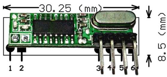
Pin 1 = Antenna
Pin 2 = Ground
Pin 3 = VCC (~3-5 volts)
Pin 4 = MEGA rx1/Pin 19 (RX Data)
Pin 5 = MEGA rx1/Pin 19 (RX Data)
Pin 6 = Ground
In combination with the WL102 transmitter:
WL102 Transmitter:
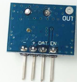
Pin 1 (-) = Ground
Pin 2 (+) = MEGA rx3/Pin 15 (TX VCC) (~2.0 - 3.6 volts !!)
Pin 3 (DAT) = MEGA tx3/Pin 14 (TX Data)
Pin 4 (EN) = Not Connected (internally connected to VCC)
SRX 882 + STX882:
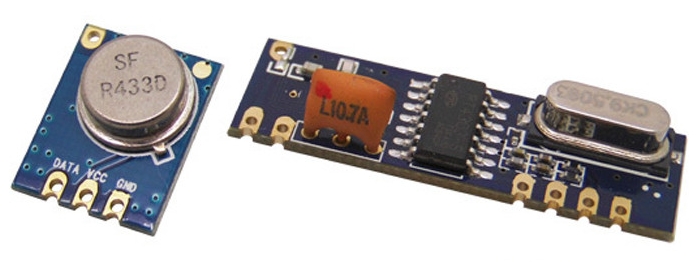
If you would like to use the SRX882 receiver and STX882 transmitter set, the pinout is:
SRX882 Receiver:
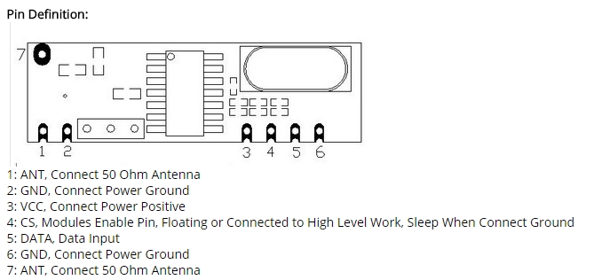
Pin 1 (ANT) = Antenna
Pin 2 (GND) = Ground
Pin 3 (VCC) = VCC (3-5 volts)
Pin 4 (CS) = Not connected
Pin 5 (DATA)= MEGA rx1/Pin 19 (RX Data)
Pin 6 = Ground
Enable module: connect GROUND to MEGA PIN7 (disable internal pullup) Read RFLink hardware configuration below!
In combination with the STX882 transmitter:
STX882 Transmitter:
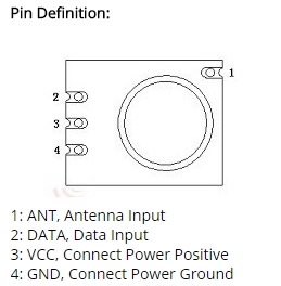
Pin 1 = Antenna
Pin 2 (DATA)= MEGA tx3/Pin 14 (TX Data)
Pin 3 (VCC) = MEGA rx3/Pin 15 (TX VCC) (~2.0 - 3.6 volts !!)
Pin 4 (GND) = Ground
New SRX 882S receiver:
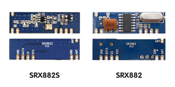
Pin 1 (ANT) = Antenna
Pin 2 (GND) = Ground
Pin 3 (VCC) = VCC (3-5 volts)
Pin 4 (CS) = VCC (3-5 volts) !!! Important !! (Thanks: Armand)
Pin 5 (DATA)= MEGA rx1/Pin 19 (RX Data)
Pin 6 = Ground
Enable module: connect GROUND to MEGA PIN7 (disable internal pullup) Read RFLink hardware configuration below!
SRX887 Receiver:
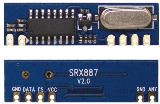
Pin 1 (ANT) = Antenna
Pin 2 (GND) = Ground
Pin 3 (VCC) = VCC (3-5 volts)
Pin 4 (CS) = Ground!! (ground connection enables SRX887 module)
Pin 5 (DATA)= MEGA rx1/Pin 19 (RX Data)
Pin 6 = Ground
Enable module: connect GROUND to MEGA PIN7 (disable internal pullup) Read RFLink hardware configuration below!
Cheap Alternative transmitter 1:
Although the XD-FST FS1000A is sufficient in most cases and many people might still have those in a drawer from an old experiment,
the Wireless-Tag RF-T-ASK is a nice alternative although hard to find. It even appears to delivers 6db more power at 5 volt than the FS1000A.
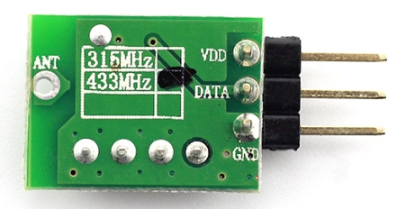
Pin 1 = MEGA rx3/Pin 15 (TX VCC) (~3 - 5.5 volts)
Pin 2 = MEGA tx3/Pin 14 (TX Data)
Pin 3 = Ground
Pin 4 (other end of the PCB) = Antenna
Note: this module appears to use 434 mhz rather than 433,92 Mhz and will be a bad choice if you also want to control RTS devices
Cheap Alternative transmitter 2:
Another cheap transmitter is the LC Technology SYN115 often found in combination with the SYN480R.
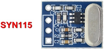
Pin 1 = MEGA rx3/Pin 15 (TX VCC) (~3 - 5.5 volts)
Pin 2 = MEGA tx3/Pin 14 (TX Data)
Pin 3 = Ground
Pin 4 = Antenna
Note: The SYN115 is producing less output power than the other modules and might be a better choice for battery operated environments
If you experience issues with the range and are not able to reach devices far away you might want to switch to a FS1000A
NOTE about 433Mhz antennas:
When you use a transceiver module like the Aurel, you have only 1 antenna pin. The Aurel module
has an internal circuit to make sure the transmit and receive part are not using the antenna at the same moment.
When you have a seperate receiver and transmitter module you will have 2 antenna pins and need to connect 2 antennas.
In that case you can not connect both antenna pins together.
A piece of solid wire with a length of 16.8 cm is a fine antenna but you can also find many 433mhz antennas in shops, ebay or aliexpress.
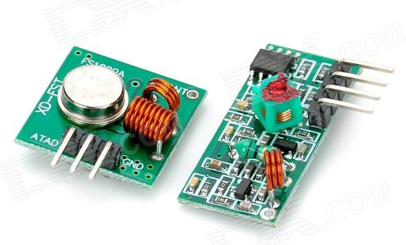
IMPORTANT NOTE about the well-known cheap Chinese set:
From the set below the transmitter (XD-FST FS1000A) is fine.
The receiver is not working very well. In most cases it receives too much noise to give stable results.
Although it will work with some devices, do not expect optimal performance.
You can try powering it with 7 volts to improve reception a bit.
Alternatively you could try the enhancements that are applied to the RXB6 in the above diagram.
You can of course use this receiver module. However, keep in mind that if you experience issues,
you really should look at one of the receivers listed above which are also not expensive.
You can find the RXB6 for less than 2 euros.
Frequent Reset issues:
In case you experience frequent reset issues you might want to try the following:
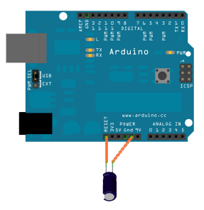
connect a 10 uF capacitor between reset and ground on the Arduino.
Simply stick the pins of the capacitor in the power connector socket.
Connect the minus pole to ground. The plus pole to reset.
This will fix any reset problems when connecting a regular Arduino Mega to a Synology NAS.
It also solve reset issues in some other cases.
The voltage of the 10uf capacitor is not really important as long as it is 5 volts or higher (12/25/50/63/240/etc. volts all are fine)
Note: When you want to update the firmware of the Arduino, remove the capacitor and reconnect it when done with the upgrade.
Alternatively you can use an Arduino Mega that has a CH340 USB chip.
NRF24L01 - "NODO NRF24L01" Sensor support:
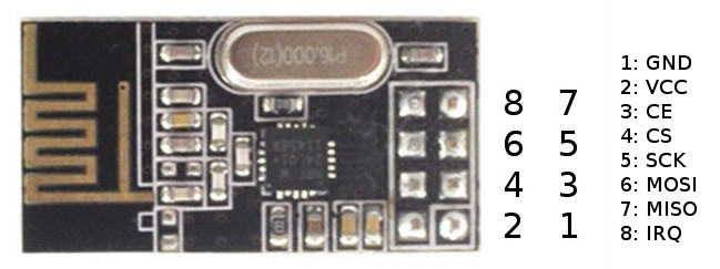
NRF = description = Mega
Pin 1 = (Ground) = Ground
Pin 2 = (VCC) = VCC (3.3 volt) Warning: Max 3.6 volt, do NOT connect to 5 volt!
Pin 3 = (CE) = VCC (3.3 volt) Warning: Max 3.6 volt, do NOT connect to 5 volt!
Pin 4 = (CS) = MEGA Pin A12
Pin 5 = (SCK) = MEGA Pin A15
Pin 6 = (MOSI) = MEGA Pin A13
Pin 7 = (MISO) = MEGA Pin A14
Pin 8 = (IRQ) = Not Connected
Antenna: This module has an onboard antenna, no additional antenna is needed.
Note that NRF24L01 for the NodoNRF and Milight use different connections.
The reason behind this is that you can use both types at the same time if you want.
NRF24L01 - MiLight / Applamp / Limitless Led support:

With the NRF24L01 transceiver module it is possible to receive from and send signals to Milight bulbs and remotes.

NRF = description = Mega
Pin 1 = (Ground) = Ground
Pin 2 = (VCC) = VCC (3.3 volt) Warning: Max 3.6 volt, do NOT connect to 5 volt!
Pin 3 = (CE) = MEGA Pin 48
Pin 4 = (CS) = MEGA Pin 49
Pin 5 = (SCK) = MEGA Pin 52
Pin 6 = (MOSI) = MEGA Pin 51
Pin 7 = (MISO) = MEGA Pin 50
Pin 8 = (IRQ) = Not Connected
Antenna: This module has an onboard antenna, no additional antenna is needed.
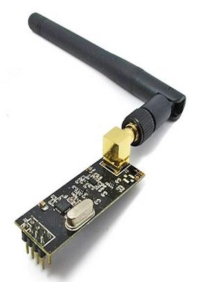
The NRF24L01 high Power version as shown below is pin compatible with the above standard NRF24L01 and is supported by RFLink.
In case you have a RFLink PCB from the Nodo shop with a version below 1.1.3, then you can use the 3.3 volt connection from the NodoNRF socket to power the NRF used for Milight
If you have a 1.1.3 or higher the NRF24L01 can be fitted directly in the socket.
In case your Arduino Mega does not supply a proper and/or powerful enough 3.3 volt
you can use an adapter board like this one:
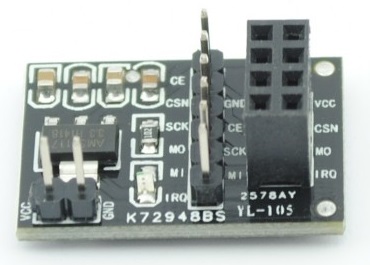
you can also place a 10 uF capacitor between 3.3 volt and ground.
Note that NRF24L01 for the NodoNRF and Milight use different connections.
The reason behind this is that you can use both types at the same time if you want.
Check the board version to see if your PCB supports the Nodo NRF or Milight NRF solution.
CC2500 - 2.4 Ghz: Philips Living Colors / Ikea Ansluta support:
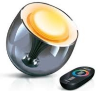
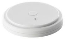
With the CC2500 transceiver modules listed below it is possible to receive and send signals to Philips Living Colors GEN1 and Ikea Ansluta devices.
Listed are 3 modules that have been tested and are working fine.
Make sure you use a proper level shifter as these modules are not designed to work with 5 volt signals.
If you experience issues you can try to put a 10 uF capacitor between 3.3 volt and ground.

CC2500:
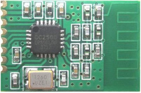
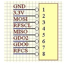
CC2500 = description = Mega
Pin 1 = (Ground) = Ground
Pin 2 = (VCC) = VCC (3.3 volt) Warning: Max 3.6 volt, do NOT connect to 5 volt!
Pin 3 = (MOSI) = MEGA Pin 51 Warning: Max 3.6 volt, do NOT connect to 5 volt I/O pin!
Pin 4 = (SCK) = MEGA Pin 52 Warning: Max 3.6 volt, do NOT connect to 5 volt I/O pin!
Pin 5 = (MISO) = MEGA Pin 50 Warning: Max 3.6 volt, do NOT connect to 5 volt I/O pin!
Pin 6 = (GDO2) = not connected
Pin 7 = (GDO0) = not connected
Pin 8 = (CS) = MEGA Pin 47 Warning: Max 3.6 volt, do NOT connect to 5 volt I/O pin!
Any Ground = MEGA PIN 6 (to unlock CC2500 software support, see the notes below!)
Antenna: This module has an onboard antenna, no additional antenna is needed.
You need a proper level shifter for the signal lines that have the warning note.
24TRGC2:
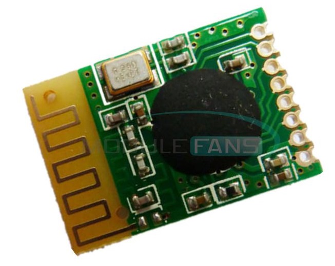
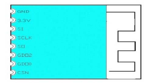
CC2500 = description = Mega
Pin 1 = (Ground) = Ground
Pin 2 = (VCC) = VCC (3.3 volt) Warning: Max 3.6 volt, do NOT connect to 5 volt!
Pin 3 = (MOSI) = MEGA Pin 51 Warning: Max 3.6 volt, do NOT connect to 5 volt I/O pin!
Pin 4 = (SCK) = MEGA Pin 52 Warning: Max 3.6 volt, do NOT connect to 5 volt I/O pin!
Pin 5 = (MISO) = MEGA Pin 50 Warning: Max 3.6 volt, do NOT connect to 5 volt I/O pin!
Pin 6 = (GDO2) = not connected
Pin 7 = (GDO0) = not connected
Pin 8 = (CS) = MEGA Pin 47 Warning: Max 3.6 volt, do NOT connect to 5 volt I/O pin!
Any Ground = MEGA PIN 6 (to unlock CC2500 software support, see the notes below!)
Antenna: This module has an onboard antenna, no additional antenna is needed.
You need a proper level shifter for the signal lines that have the warning note.
WLC24D:
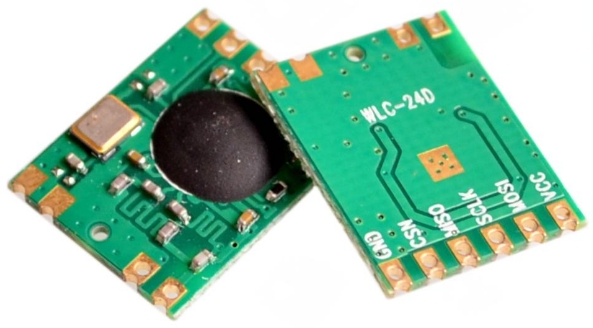
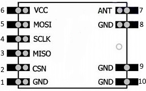
CC2500 = description = Mega
Pin 1 = (Ground) = Ground
Pin 2 = (CS) = MEGA Pin 47 Warning: Max 3.6 volt, do NOT connect to 5 volt I/O pin!
Pin 3 = (MISO) = MEGA Pin 50 Warning: Max 3.6 volt, do NOT connect to 5 volt I/O pin!
Pin 4 = (SCK) = MEGA Pin 52 Warning: Max 3.6 volt, do NOT connect to 5 volt I/O pin!
Pin 5 = (MOSI) = MEGA Pin 51 Warning: Max 3.6 volt, do NOT connect to 5 volt I/O pin!
Pin 6 = (VCC) = VCC (3.3 volt) Warning: Max 3.6 volt, do NOT connect to 5 volt!
Any Ground = MEGA PIN 6 (to unlock CC2500 software support, see the notes below!)
Antenna: Note that this module does not have an antenna. You need to connect one to the antenna pin!
Without antenna you will most likely not receive anything.
If you do not have an antenna, use a piece of wire. The length of this wire should be between 26 and 32 millimeters.
You need a proper level shifter for the signal lines that have the warning note.
Note about the partially double use of connections/pins:
Indeed the CC2500 and NRF modules use partially the same pins, this is not a mistake but a feature!
Because of that we can talk to multiple modules.
RFLink Hardware & Software Configuration:
Since there were some issues with the detection of the CC2500 modules, the software settings enabling hardware device support have changed starting with RFLink release 46. The same method is now also followed to make some other settings.
CC2500:
You need to connect Arduino PIN 6 to ground in order to unlock CC2500 device support.
You also still need to enable Ansluta or Living Colors if you want to use these protocols.
Tested level converters:
Converter 1) Preferred choise:
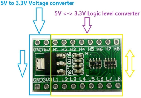
link
Converter 2)
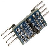
Note: best is to use 2 of these to wire all lines
link
Converter 3)
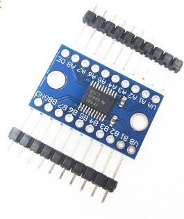
Note: connect Mega's 5 volt to VB
Connect Mega ground to GND and connect the CC2500 to ground
connect Mega 3.3 volt to the VA line
connect a 10K resistor from OE to 3.3 volt
connect the mega SPI lines to one of the other free B lines
connect the CC2500 signal lines to the A lines matching the B lines
link (Actually received TXB0108 although TXS is advertised)
link New Link ..
Pullup on RF data in pin:
Connect Arduino PIN 7 to ground in order to disable an internal pullup on the RF data pin.
This is required for some RF modules like the SRX882.
Reset of EEPROM settings
Connect Arduino PIN 12 to ground in order to reset settings that are stored in EEPROM.